| |
|
Ballast Water Treatment Systems |
|
|
| TWO SYSTEMS – MULTIPLE SOLUTIONS – ONE WAY TREATEMENT |
| |
| 1. THROUGH FLOW ELECTROLYSIS-ELECTROCLEEN ™ (ECS) |
| |
|
| |
|
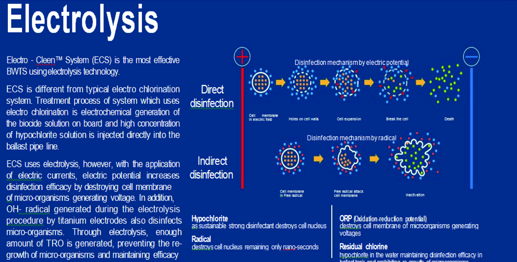
Techcross Electro-Cleen ™ System (ECS) is one of the most effective ballast water
management systems utilizing electrolysis. ECS treats all incoming ballast water by
in-situ production of hypochlorite with combined effects of electric shock and hydroxyl radical in
the Electro Chamber Unit (ECU). This simple disinfection processing is so powerful
that it destroys cell membrane of microorganisms and prevents re-growth, needing only
one-time treat-ment. It means ECS contributes to reduction in time and operating
cost. Techcross has upgraded ECS through continuous research and development involving
and approvals with Classification Societies and Flag States to better performance.
|
| |
 |
 |
 |
 |
 |
 |
IMO Final
Approval
2008 |
Korean
Government
2008 |
KR Type
Approval
2008 |
Liberian Flag
2011 |
ABS Type
Approval
2011 |
Japanese Flag
2012 |
| |
|
|
|
|
|
 |
 |
 |
 |
 |
 |
RS Type
Approval
2013 |
BV Type
Approval
2013 |
RINA Type
Approval
2013 |
Cyprus
2014 |
Lloyds Register
2015 |
Australia Flag
2016 |
| |
|
|
|
|
|
 |
 |
 |
 |
 |
 |
DNV&GL Design
Assessment
2016 |
CCS Type
Approval
2017 |
Danish
Government
2017 |
Greece Flag
2017 |
Panama Flag
2017 |
USCG T.A
2018 |
|
|
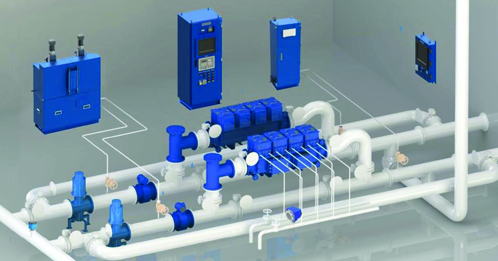
| ELECTRO-CLEEN ™ SYSTEM |
| |
|
|
-
ECU (Electro Chamber Unit)
-
TSU (TRO Sensor Unit)
-
PDE (Power Distributor Equipment)
|
-
ANU (Auto Neutralization Unit)
-
CPC (Control PC)
-
T-strainer
|
-
FMU (Flow Meter Unit)
-
CSU (Conductivity Sensor Unit)
-
FTS (Freshwater Temperature Sensor)
|
|
| Ballasting |
|
|
CSU |
 |
FMU |
|
T-strainer |
|
ECU |
|
PDE |
|
TSU |
|
Ballast Tank
|
|
|
|
All the incoming ballast water passes through T-strainer before it is treated by ECU.
ECU can disinfect marine organisms in the ballast water with one time treatment during ballasting.
|
|
| Deballasting |
|
|
|
|
|
A main process during deballasting operation is neutralization of the treated water by ANU.
ANU is designed to automatically neutralize the treated water according to data about flow rate and TRO concentration by FMU & TSU.
|
| |
| Advantages of ECs |
| |
-
Strong disinfection efficacy
-
Low power consumption
-
Low operational costs
-
Largest reference list
-
Convenient installation and maintenance
-
Automation of system
-
Global network
|
|
SPECIFICATION OF ECS
|
|
|
Specific information of Electro-Cleen™ System |
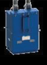
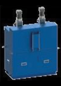
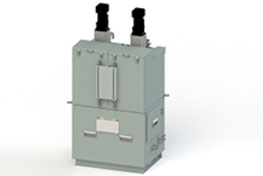
| ECU (Electro Chamber Unit) |
| |
|
|
Specification |
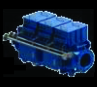
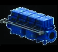
ECU is the core component killing marine organisms in the ballast water ranging from ECU 150B to ECU 1000B. Each model can be
combined in parallel to achieve higher TRCs (Treatment Rated Capacity). |
|
Size |
ECU 150B |
W790 X D540 X H862 (mm), 390kg |
|
ECU 300B |
W1,243 X D763 X H862 (mm), 490kg |
|
ECU 450B |
W1,490 X D763 X H862 (mm), 660kg |
|
ECU 600B |
W1,840 X D763 X H862 (mm), 830kg |
|
ECU 1000B |
W2,000 X D1,124 X H914.5 (mm), 1,210kg
|
|
Power Supply |
AC 440V, 3ph, 60Hz (FROM PDE) |
|
Component
|
EM(Electro Module), PRU(Power Rectifier Unit), EPJ(ECU Power Junction box), ESJ(ECU Signal Junction box) |
|
Ex-Certificate
|
Ex II 2 G Ex de IIB T4 Gb : LCIE 12 ATEx 3095X / Ex de IIB T4 Gb : IECEx KGS 12.0008X |
|
|
|
|
|
|
|
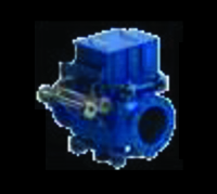
< ECU 150B >
|
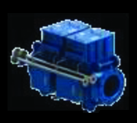
< ECU 300B >
|
< ECU 450B >
|
< ECU 600B >
|
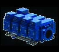
< ECU 1000B >
|
|
|
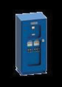
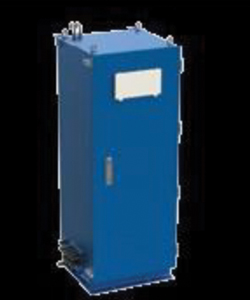
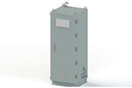
| PDE (Power Distributor Equipment) |
| |
|
|
Specification |
PDE supplies AC 440V from the ship to all other components of ECS and controls communications of
all other components. |
|
Size |
PDE 12A |
W600 X D630 X H1,500 (mm), 175kg |
|
PDE 24A |
W700 X D700 X H1,900 (mm), 310kg |
|
PDE A4 |
W700 X D530 X H1,500 (mm), 250kg |
|
Power Supply
|
AC 440V, 3ph, 60Hz / AC220V, 60Hz |
|
|
|
|
|
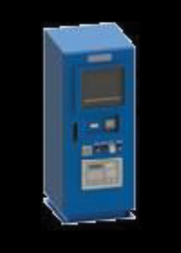
< PDE 12A >
|
< PDE 24A >
|
< PDE A4 >
|
< ANU 5T >
|
< ANU 10T >
|
|
|
| ANU (Auto Neutralization Unit) |
| |
|
|
Specification |
ANU is designed to automatically neutralize treated ballast water prior to its discharge so that the discharge of
Residual Biocides may not exceed 0.1ppm (instantaneous maximum limit) according to TRO level measured by TSU.
|
|
Size |
ANU 5T |
W800 X D733 X H1,655 (mm), 220kg |
|
ANU 10T |
W1,200 X D733 X H1,655 (mm), 308kg |
|
Power Supply
|
AC 220V, 60Hz (FROM PDE) |
|
Neutralizer
|
Sodium Thiosulfate |
|
Mixture Ratio
|
2 (Fresh water) : 1 (Neutralizing agent) |
|
Tank Capacity |
ANU 5T |
100 Liter for each tank (Both : 200 Liter) |
|
ANU 10T |
200 Liter for each tank (Both : 400 Liter) |
|
|
|
|
 |
|
TSU (TRO
Sensor Unit) |
|
Specification |
TSU measures
concentrations of TRO (Total
Residual Oxidant) generated by ECU
during ballasting operation. TSU
also checks the TRO level in the
treated ballast water for proper
neutralization of ballast
water before its discharge. |
|
Size |
W470 X D450 X
H1,347 (mm), 100kg |
|
Power Supply
|
AC 220V, 60Hz
(FROM PDE) |
|
Ex-Certificate |
II 2 G Ex px
IIC T4 Gb / ITS11 ATEx 17384 |
|
|
|
|
|
 |
|
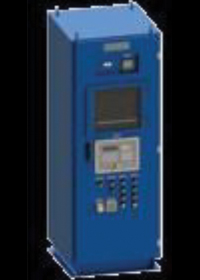
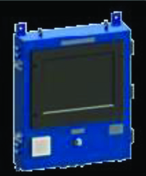
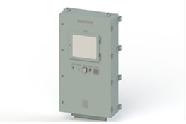
CPC (Control PC &
S/W) |
|
Specification |
Control PC features an
upgraded touchscreen interface which is easy
& simple to operate ECS. In addition, the
CPC shows all the data saved relating to ECS
operation. |
|
Size |
W480 X D119 X H660
(mm), 35kg |
|
Power Supply
|
AC 220V, 60Hz (FROM PDE) |
|
|
|
|
 |
|
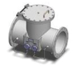
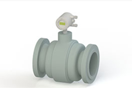
T-strainer |
|
Specification |
T-strainer with a 3mm
mesh filter is used during ballasting
operations to filter out large marine
species and foreign materials in the
incoming ballast water. It helps protect
electrodes inside the
ECU to maintain an optimal performance of
ECU for a strong disinfection efficacy. |
|
Size |
W550 X D366 X H503
(mm), 87kg |
|
Type |
Straight, Angle |
|
Pressure Range |
-1 ~ 10 Bar |
|
|
|
|
 |
|
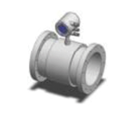
FMU (Flow Meter
Unit) |
|
Specification |
Measures flow rate of
ballast water during ballasting and
deballasting operation. |
|
Power Supply
|
AC 220V |
|
|
|
|
 |
|
FTS (Freshwater
Temperature Sensor) |
|
Specification |
Measures temperature of
cooling water supplied to a rectifier from
vessel. |
|
Power Supply
|
DC 24V |
|
|
|
|
 |
|
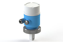
CSU (Conductivity
Sensor Unit) |
|
Specification |
Measures electrical
conductivity of seawater passing through ECU
during ballasting operation. |
|
Power Supply
|
DC 24V |
|
|
|
|
 |
|
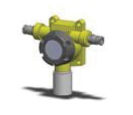
GDS (Gas Detection
Sensor) |
|
Specification |
Detects a possible leak
of hydrogen gas from ECU. |
|
Power Supply
|
DC 24V |
|
|
|
|
|
|
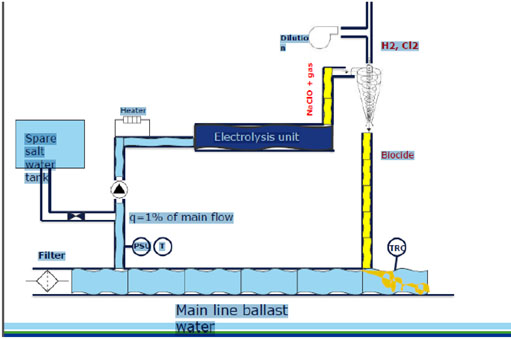
2. Electro-Chlorination Technology – Slip Stream Method
Disinfection principle——Core technology
When seawater flows through the
electrolyzer, decomposition reactions take place on
the electrode surfaces, with chlorine produced at
the anode and hydrogen gas at the cathode. Chlorine
gas can be dissolved in water to produce
hypochlorous acid and hydrochloric acid rapidly:
|
Cl2 + H2O → HOCl + Cl- + H+
So the whole reaction is:
NaCl + H2O → NaOCl + H2↑
Sodium hypochlorite solution as a very effective
germicide can be kept in ballast water for a certain
period to effectively kill the plankton, spores,
larvae and pathogens contained in the ballast water.
|
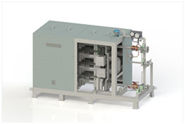
ECS-HYCHLORTM
SYSTEM
TECHCROSS HYCHLOR ELECTROCHLORINATION – SIDE STREAM
DOSING SYSTEM
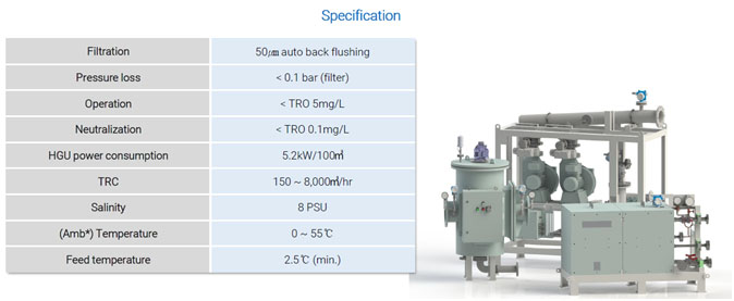
The
ECS-HYCHLORTM System adopts a disinfection technology combining
filtration with indirect eletrolysis. It consists of filtration, electro
chlorination unit and neutralization units with some of accessories.
The filter unit is mounted directly on the main ballast pipeline to eliminate
larger microorganisms and suspended solid than 50㎛
in size. The organisms and solids are filtered out by filtration unit and
discharged along with ambient water, using auto back-flushing function. During
de-ballasting, ballast water does not pass through the filtration unit.
The indirect electro chlorination unit operates only during ballasting to
disinfect microorganisms filtered out at first by the filtration unit. Only 1%
of total ballast water flows to the electro chlorination unit to be used to
generate the highly concentrated TRO. This concentrated TRO is injected to the
main ballast line to be mixed with the rest of ballast water and maintain
maximum TRO concentraion of 5.0mg/L.
The neutralization unit neutralizes the residual TRO by using sodium thiosulfate
as the neutralizing agent before discharging the treated water overboard during
de-ballasting. The maximum allowable discharge concentration of TRO is 0.1mg/L.
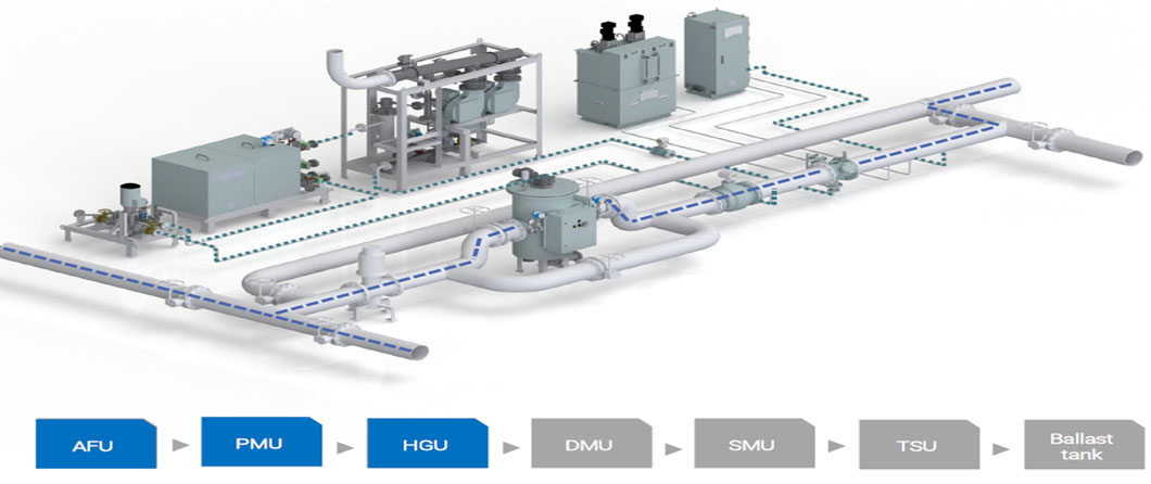
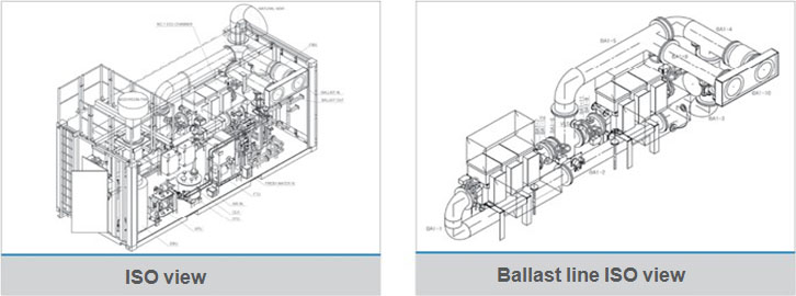
F:LOW DIAGRAM - BALLASTING
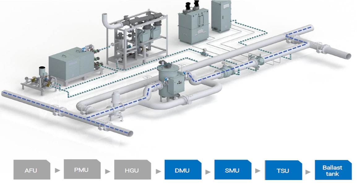
F:LOW DIAGRAM - DEBALLASTING
|
|
Main Equipment |
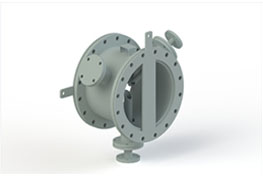
AFU (Auto Filter Unit)
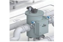
Removes particles >50㎛ during ballasting.
The head loss by the unit is below 0.1 bar
and negligible |
|
HGU (Hypochlorite Generation Unit) Main
Equipment – Electrochlorination
HGU is indirect electrolysis component in
the form of side stream. It generates
oxidants by electro chlorination and
disinfects microorganisms filtered out by
AFU. |
| |
|
|
DMU (Degas Module Unit)
Dilutes and discharges H2 gas, which is
generated during electrolysis, by an air
vent valve and a blower. It is composed of
safe components which are approved the
explosion-proof certification.
|
|
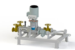
SMU (Static Mixer Unit)
Injects high concentrated TRO to the main
ballast pipeline for the dilution by side
stream method during ballasting and injects
neutralizing agent during de-ballasting. |
|
|
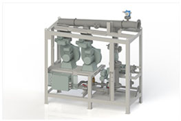
Supporting Equipmen |
PMU (Pump Module Unit)
Delivers 1% of sea water to the Electrode
Module through main ballast pipeline by the
pump. It is composed of a pump, an auto
control valve and a flow meter. |
|
ANU (Auto Neutralization Unit)
Before discharging the treated water
overboard, ANU doses neutralizing agent to
maintain TRO concentration with below
0.1mg/L during de-ballasting only. |
| |
|
|
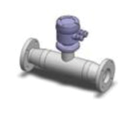
TSU (TRO Sensor Unit)
Measures TRO concentration during ballasting
and de-ballasting. TSU is controled by HMI.
|
|
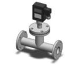
Sensors - FMU (Flow Meter Unit)
Measures flow rate of ballast water during
ballasting and de-ballasting. |
| |
|
|
Sensors - CSU (Conductivity Sensor Unit)
Measures electrical conductivity of seawater
during ballasting operation |
|
Others - Local Control Unit
 |
| |
|
|
|
| |
|
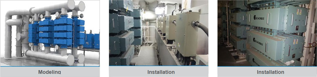
INSTALLATION REFERENCES |
Case 01 [New building
: SKID mount type]
 |
| |
|
Specification |
|
|
|
|
Division |
Specification |
Division |
Specification |
|
Ship type |
170K LNG |
Model |
ECS 2600B X 2sets |
|
Class |
DNV |
Installation location |
E/R |
|
Capacity |
5200㎥/h X 1set |
Date |
2013 |
|
|
|
|
|
|
| |
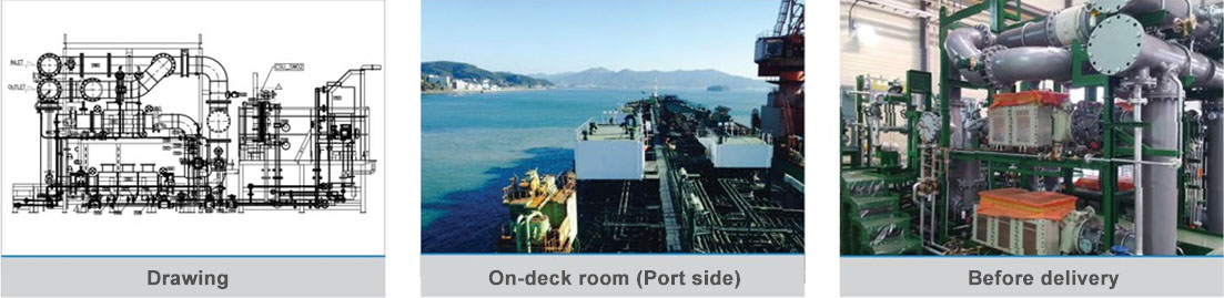
Case 02 [New building
: On-deck room]
 |
| |
|
Specification |
|
|
|
|
Division |
Specification |
Division |
Specification |
|
Ship type |
37K PC Tanker |
Model |
Ex-ECS 750B X 2sets |
|
Class |
KR |
Installation location |
On-deck |
|
Capacity |
750㎥/h X 2sets |
Date |
2014 |
|
|
|
|
|
|
| |
|
Case
03 [New building & Retrofit : Container SKID] |
 |
|
Specification |
|
|
Division |
Specification |
|
Ship type |
Tanker |
|
Container
size |
20ft |
|
Model |
Ex-ECS 900B
X 1set |
|
Installation location |
On-deck |
|
|
|
|
|
| |
|
|
|
| |
|
|
|
|